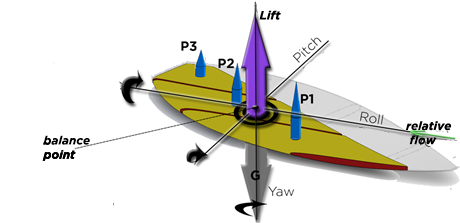
Yaw rotations are induced by various causes::
- the movements of the surfer around his vertical axis. This vertical axis of rotation of the body of the surfer can be at the level of the back foot or at the level of the spine for more fluid maneuvers.
- The variation in the grip of the rail along its length the distribution of frictional forces under the board surface
- and the work of the fins
YAW ANGLE VARIATION (ACTION ON THE DRIFT ANGLE) RESULTING FROM THE ELEMENTAL PLANING FORCES OF THE SHAPE :

Let us schematize in the plane of rotation of Yaw(yaw) the forces and torques generated by the two elements El.1 and El.3. The forces F1 and F3 are the resultant of the drag forces of planing, rail, and friction, respectively identified in the diagram below, by Fp, Fr and Fc whose indices 1 and 3 indicate the element.

The distances d1 and d3 designate respectively the lever arm linking the force F1 and F3 to the axis of yaw rotation. The moment, in G, of rotation in yaw of the board, results from the moment of the element 1 and 3 respectively defined by
MG(F1)= F1 x d1 and
MG(F3)= F3 x d3. Equation 65
If MG(F1) <> MG(F3) lthe board rotates around the yaw axis passing through point G. The rotational speed variation of Yaw (acceleration yaw) is given by
Acceleration yaw(rad/s²) = (MG(F1) + MG(F2) + MG(F…)) / moment of inertia yaw. Equation 66
The calculation of the moment of inertia of yaw is given in the appendix). To fully define the spin speed (= rotation speed of yaw), we will have to integrate in the sum of the moments of the elements of the shape, the moments generated by the fins (detailed in the following paragraph)
The angular speed of rotation yaw can be updated according to the time interval dt:
V_yaw(rad/sec) = V_yaw + dt*acceleration_yaw. Equation 67
THE YAW AXIS FIN MOMENT (ACTION ON THE DRIFT ANGLE) :

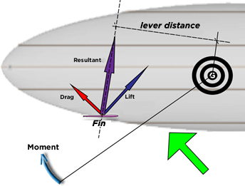
- The aileron drag is by definition parallel to the flow, therefore parallel to the Yaw plane. projected drag = aileron drag
- Projection of the lift in the plane of yaw: the lift is by definition perpendicular to the flow and perpendicular to the generatrix of the aileron. The projection of the lift in the plane of rotation of yaw is: Projection lift = Cosine (cant angle) * lift
- The resultant force (N) of the aileron in the plane yaw = sqrt (Projection lift^2+drag^2)
- The point of application of the resultant is moved by the cant
- the lever length is the distance between G and the line passing through the resultant.
- Moment = Yaw lever distance * résultante
Effect of rail on yaw rotation::
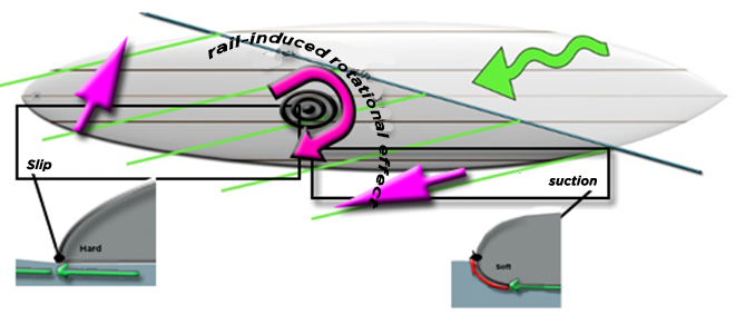
The shape of the rail can generate suction forces (see rail and boundary layer), The distribution of the rail shapes can generate yaw rotation torque: A "soft" rounded front rail area catches the rising flow of the wave, the board is sucked into the wave and helps the surfer in his search for acceleration in allowing a higher board position in the wave, where the still point offers the maximum potential energy. The surfer will thus be able to choose a downward angle of incidence to accelerate if he wishes, but he will be free to go up. The shaper thus has a means of generating a force for maintaining the rail in the relative flow, which he can dose to suck up or let the chosen rail zones slide: By letting the fluid escape freely from the rail in the zone of the tail, we favor a natural drift angle of the board, to use the drive of the fins (if they are correctly oriented) and obtain a lower planing surface/submerged width ratio and obtain better planing performance. (see Lindsay Lord)
